Subscribe me on YouTube

Sunday, May 15, 2016

Cisco Router Rommon Mode Problem_How to Get a Cisco Router Out of Rommon Mode_Cisco Router Rommon Recovery_Configuration Register Value 0xF_Cisco 1812 Router Restarts Frequently

Hi, I'm Sujoy from India and today I'll tell you how to recover a Cisco router from Rommon> mode. Also tell you how to recover a Cisco switch from Switch: mode.
Do you know Cisco 1812 router can restart frequently if the config-register value is misconfigured to 0x2102 instead of 0xF.

What is Rommon?
Rommon> or ROM MONitor is the bootstrap loader program stored in ROM (Read Only Memory) of Cisco Router. Which does basic things such loading IOS and booting the router. Another thing is Configuration Register, this is a software register which tells Cisco router what to do during boot. By changing configuration register value, we can do useful things such as password recovery of Cisco router. Cisco router can enter rommon mode for few reasons-
  1. Configuration register value modified
  2. Break (system interrupt) is given during boot (by Ctrl+Pause/Break)
  3. IOS file is corrupted or missing or unsupported
I recently faced a problem where customer lodged complaint that Cisco router is not reachable from remote via telnet or SSH, router can not be pinged also. But the router is powered on. When connected console with router, I found that the router is in rommon 1> mode.

You can type ? (question mark) and press enter to see available commands in rommon mode.
I wanted to if there is an IOS file present in flash memory (cisco router stores IOS file in Flash Memory).
I given command- dir flash: and saw that IOS file present is- c181x-advipservicesk9-mz.124-24.T5.bin

I instructed router to boot from that IOS file using command- boot flash:c181x-advipservicesk9-mz.124-24.T5.bin

Router booted and entered into Router> prompt (or hostname> prompt here). It may ask for username & password if configured.

Type enable and press enter to go to Router# prompt. It may ask for enable password if configured.
Now type config t and press enter to go to Router(config)# prompt. Then give command- do dir to see available files in flash memory. Then select and copy the IOS file name. Now give command- boot system flash:c181x-advipservicesk9-mz.124-24.T5.bin

Next to check configuration register value, give command- show version
Last line shows configuration register value. Default configuration register value on Cisco router is 0x2102 and on Cisco switch it's 0xF .But this is old router (Cisco 1812) which has 10 fast ethernet ports, much like a switch, so default configuration register value is 0xF
Solution- This router had the configuration register value set to 0x0 that's why it was going to rommon mode every time it's reloaded. Change it to 0xF


Router#config t
Router(config)#
Router(config)#do dir
Router(config)#boot system flash:c181x-advipservicesk9-mz.124-24.T5.bin
Router(config)#config-register 0xF
Router(config)#do wr
Then reload the router. Router should boot into Router mode this time.
On other Cisco routers, change configuration register value to 0x2102 for normal operation.
On Cisco Switches, change configuration register value to 0xF for normal operation.

Configuration Register Values and Their Meaning-
0x2102 = Load IOS from flash and load startup-config from NVRAM. (default value)
0x2142 = Load IOS from flash but don't load startup-config from NVRAM. (Router will go into setup mode, asking you to enter initial configuration. Used for password recovery.)
0x2100 = Directly go to Rommon mode
0x2101 = Load Mini IOS from bootflash/ROM (not available on all models)

But what if the IOS file is missing/corrupted on flash memory? Then you've to use TFTPDNLD to recover it. Below are links to my video tutorials on YouTube.

Cisco Router Romon Recovery by tftpdnld- https://youtu.be/7ZjIWMdtmMc
Cisco Router Password Recovery- http://youtu.be/_jPnlAV6NR8
Cisco Router Initial Configuration and WAN Setup- http://youtu.be/saqDIaUDC9g
Cisco Catalyst Switch Password Recovery- https://youtu.be/i1bbWiPosRM
Cisco L3 Switch IOS Upgrade- https://youtu.be/F7dLK1IB-ko
Tellabs Leased Line Modem & Cisco Serial Interface Troubleshooting- https://youtu.be/TuPWULL4V8o

ONE ANNOUNCEMENT!
====================
I'm a YouTube Partner from India. I've uploaded videos on Statistics,Numerical Methods,

And a series of videos showing how to use your scientific calculators Casio fx-991ES & fx-82MS to do maths easily.

Click my YouTube channel's link below to watch them.
Subscribe to my youtube channel below-

 http://www.youtube.com/sujoyn70

Please 'SUBSCRIBE' to my YouTube channel to get updates about my latest video uploads!

Thursday, May 5, 2016

ISDN PRI Troubleshooting and RJ-48 Ethernet Loopback Test on Cisco Router_Primary Rate Interface Problem Fixed_NetworkingTelecom Field Engineer Guide

Hi, I'm Sujoy and today I'll show you how to troubleshoot ISDN Primary Rate Interface (PRI) line and determine working status of ISDN PRI Multiflex Voice WAN Interface Card on Cisco router.

I recently faced a problem where customer can't communicate over the ISDN PRI leased line. I had to do a loopback test on PRI interface to determine if the problem is with ISDN PRI line or PRI card on Cisco 2921 Router. I'll show you how to do step by step troubleshooting.

Step 1- Look at the picture below. It shows VWIC2-1MFT-T1/E1 card on Cisco 2921 router.
VWIC2-1MFT-T1/E1 stands for Voice WAN Interface Card v2 - 1 Port Multiflex Trunk T1 or E1 line card.


Check physical layer status, first look at the card and the interface. If the Ethernet cable is connected and LEDs are glowing then the interface is up. If cable is not connected, connect the cable coming from PRI adaptor and check if interface is up. If not up, check if interface is administratively down and check other configuration.

Step 2- Below is the picture of PRI-to-Ethernet adaptor which converts ISDN line to standard RJ-48 Ethernet line for terminating to Cisco router.


Check the PRI to Ethernet adaptor if any wire got disconnected. If not, we'll move on to Router troubleshooting.

Step 3- Establish a console or telnet session with router and go to Router# prompt (privilege mode). Give command- show inventory and check if the PRI card is showing in inventory. In our case, it's detecting and is highlighted in picture below. If it's showing, then the card is assumed to be ok.

Step 4- Now from Router# prompt give command- show isdn status and check layer 1 status. In our case, layer 1 is SHUTDOWN. If layer 1 (physical layer) is SHUTDOWN, then layer 2 (data link layer) and layer 3 (network layer) will not be able to function.

Layer 1 can be SHUTDOWN due to few reasons- 1) Card is faulty 2) Signaling or keepalives not being received from ISP side 3) wrong configuration 4) Ethernet cable not connected 5) Interface is administratively down. I know reasons 4 and 5 are not valid. I've to identify reasons 1, 2 and 3.

Step 5- Check running-configuration. From Router# prompt give command- show run and gather few information shown in below picture.
card type
controller type
serial interface number
voice-port number

Check if any recent configuration changes have been done. If there are no recent configuration changes done on router before PRI line went down, then it can be issues with PRI card or line. You can check that by command- show run

Router# show run
Building configuration…
Current configuration : 9363 bytes
!
Last configuration change at 13:54:46 IST Wed Apr 20 2016 by Admin

If no configuration changes are done, then we'll move on to loopback test.

Step 6- Check controller status. From Router# prompt give command- show controller e1 0/0/0 and check status up/down. Notice in line number 7, Framing is NO-CRC4 and Line Code is HDB3. These values are generally ISP provided and cause line down if mismatch. Try changing them and see if this works.
Also check if controller, serial interface, voice port is administratively down. If so, enable them by no shutdown command.

Step 7- If that did not work, we need to do loopback test to identify if the problem is with router & card or ISP/telco PRI line.

For this test, I need a Ethernet Loopback Plug. How to make Ethernet Loopback Plug ? Take any ethernet cable and cut after three inch. Now hold the RJ-45 plug keeping pins below and locate pin 1,4, 2, 5. Peel plastic cover of above pins and short copper wires together. Short pin 1 and 4 together and pin 2 and 5 together. Bend slightly outward to avoid short circuit between this two couplings.


Step 8- Connect the loopback plug to PRI interface. And check if LED is glowing. If not, wiring is wrong.


Step 9- Now for loopback test we'll look at the running-config. We derived it in step 6.
In our case, card type e1 0 0 (means e1 card, slot 0 and subslot 0), controller e1 0/0/0 (same as card type,device/slot/subslot), interface Serial0/0/0:15 (it's virtual serial interface for communication), voice-port 0/0/0:15 (voice ports). Give below commands-

Router#config t
Router(config)#controller e1 0/0/0
Router(config-controller)#no pri-group timeslots 1-31
If the above command is accepted, then ok. Otherwise you've to do few more steps.
Router(config-controller)#no pri-group timeslots 1-31
%controller must be shutdown before unconfiguring pri-group to gracefully bring down isdn.
Router(config-controller)#shutdown


Step 10- Shutting down the voice interface. If it gives an error like the one below-
%voice interface must be shutdown before deleting pri-group.
Then give below commands-
Router(config-controller)#exit
Router(config-controller)#voice-port 0/0/0:15
Router(config-controller)#shutdown


Step 11- Removing layer 3 binding.  If it gives an error like the one below-
%Remove layer 3 binding first
Then give below commands-
Router(config-controller)#exit
Router(config-controller)#int Serial0/0/0:15
Router(config-controller)#no isdn bind-l3 ccm-manager

Router(config)#controller e1 0/0/0
Router(config-controller)#no pri-group timeslots 1-31
This time the pri-group command will be accepted. Sometime you may have to give below command to create the serial 0 interface.
Router(config-controller)#channel-group 0 timeslots 1-31

Step 12- Assigning IP address for loopback test.
Router(config-controller)#exit
Router(config)#int Serial0/0/0:0
Router(config-if)#encapsulation hdlc
Router(config-if)#ip add 10.10.10.10 255.255.255.0
Router(config-if)#no shutdown


Step 13- Checking Serial Interface status and enabling controller e1.
Router#show int Serial0/0/0:0
Router#config t
Router(config)#controller e1 0/0/0
Router(config-controller)#no shutdown


Step 14- Doing loopback test.
Router#ping ip 10.10.10.10 repeat 1000
If all 1000 pings are getting reply (!) then your PRI card interface is working fine. The problem is with the line. Contact your ISP/telco for line checkup. You can also check that the show controller e1 0/0/0 shows status up.

You can watch video version of this article here- https://youtu.be/rJJGAi-Sdy0

ONE ANNOUNCEMENT!
====================
I'm a YouTube Partner from India. I've uploaded videos on Statistics,Numerical Methods,

And a series of videos showing how to use your scientific calculators Casio fx-991ES & fx-82MS to do maths easily.

Click my YouTube channel's link below to watch them.
Subscribe to my youtube channel below-

 http://www.youtube.com/sujoyn70

Please 'SUBSCRIBE' to my YouTube channel to get updates about my latest video uploads!

Tuesday, May 3, 2016

How to Subnet? Subnetting in a Nutshell for Dummies! Learn Subnetting in 10 Minutes!! [Everything Explained]

Hi, I'm Sujoy from India and today I'll tell you how to solve any subnetting practice questions easily! You may be preparing for your CCNA exam or want to learn everyday subnetting. I'll tell you how to subnet in your head easily.

IP Address Basics- An IP address is a 32 bit binary number, represented in 4 blocks of 8bits each. Each 8bit block is called an Octet. For human comprehension, each octet is written in Decimal form, separated by dots. This representation is called 'Dotted-Decimal Representation'. IP addresses are of 5 'classes', which is generally identified by 1st octet of an IP address.
Class A (0-127), Class B (128-191), Class C (192-223), Class D (224-239), Class E (240-254).
Example- 192.168.1.115, which is Class C address, since first octet 192 falls within range (192-223).

Subnet Mask Basics- Subnet Mask is a 32 bit binary number. Just like IP address, the subnet mask is also represented in 4 blocks of 8bits each. Subnet mask, when written with an IP address, represents which subnet the given IP address belongs. Example- 255.255.255.224 or /27. Here /27 means out of 32 bit subnet mask, first 27 bits are reserved from left.
Subnet Mask Categorization- /8-/15 only for Class A, /16-/23 Class A & B, /24-/30 Class A, B & C.

Let's take a question- 192.168.1.115/27. I'll tell you how to do Eleven subnetting calculations easily.

Weighted Binary Chart (represents an octet)
 27    26   25   24    23  22  21  20
128   64    32    16     8     4     2     1

Let's Begin the Calculation!

1. Subnet Mask- The given ip address is 192.168.1.115, which is Class C IP address, means first 3 octets or 24bits of subnet mask is already reserved (which is 255.255.255.0). Now there is /27, means 27-24 = 3 more bits are reserved from 4th octet. Total 27 bits are reserved.
Now from Weighted Binary Chart, if we reserve 3bits from left, the mask value will be 128+64+32 = 224. So complete subnet mask for this subnet = 255.255.255.224.

2. Block Size- Block size is 2^unreserved bits. Here in 4th octet, 3 bits are reserved. Unreserved bits 8-3 = 5. From Weighted Binary Chart, 2^5 = 32, so block size is 32. Block size is very important.

3. Network ID/Network Address- Now we will count in block of 32, which is our block size.
0-32-64-96-128-160-192-224-256. 4th octet of our IP address is 115, which falls in range 96-128. So our network ID is 192.168.1.96 (by starting value of range).

4. Broadcast Address- It's the last IP address of the subnet. Our range is 96-128. Last IP address is 127, because from 128 next subnet starts (128-160). Broadcast address = 192.168.1.127.

5. Start IP Address- It's the first IP address after Network ID. In our subnet, Network ID is 96, so Start IP address = 192.168.1.97.

6. End IP Address- It's the last IP address before Broadcast Address. In our subnet, Broadcast Address is 127, so End IP address = 192.168.1.126.

7. Range of Valid Assignable IP Addresses for This Subnet- 192.168.1.97 - 192.168.1.126.
These IP addresses can be assigned to host devices (such as PCs in that subnet).

8. Number of Subnets- It's given by 2^reserved bits. Reserved bits are 3, so number of subnets = 2^3 = 8. Let's look at this, 0-32-64-96-128-160-192-224-256. Our first subnet is 0-31, next is 32-63, and so on, total 8 subnets.

9. Number of Hosts Per Subnet- It's given by (2^unreserved bits - 2). Or Block Size - 2. Unreserved bits are 5, and 2^5 is 32 (which is our block size). And 32-2 = 30 hosts per subnet. Let's verify!
Our valid IP address range is 192.168.1.97 - 192.168.1.126. If you count to 126, starting from 97, you'll count 30 addresses.

10. IP 192.168.1.115 is in Which Subnet? It's is fourth subnet. Our first subnet is 0-31, second is 32-63, third is 64-95, fourth is 96-127. IP 192.168.1.115 falls in 4th subnet.

11. Represent 192.168.1.115 in Binary- As I mentioned earlier, an IP address is actually a binary number. Let's write each octet in binary format. We'll use Weighted Binary Chart for this calculation.

128   64    32    16     8     4     2     1
  1      1      0      0      0     0     0     0  =  192
  1      0      1      0      1     0     0     0  =  168
  0      0      0      0      0     0     0     1  =    1
  0      1      1      1      0     0     1     1  =  115

So the binary representation is- 192.168.1.115 = 11000000.10101000.00000001.01110011
Here's the logic- to make 192 (1st octet), we need 128+64=192. We've taken those two bits, and placed '1' below 128 and 64 in Weighted Binary Chart. We didn't take any other bits so we placed 0 below them.
Similarly for 168, we've taken 128+32+8 = 168. So we've placed '1' below 128, 32 and 8, and so on.

You can watch video version of this article here- https://youtu.be/91ZZ7xVLjmU


ONE ANNOUNCEMENT!
====================
I'm a YouTube Partner from India. I've uploaded videos on Statistics,Numerical Methods,

And a series of videos showing how to use your scientific calculators Casio fx-991ES & fx-82MS to do maths easily.

Click my YouTube channel's link below to watch them.
Subscribe to my youtube channel below-

 http://www.youtube.com/sujoyn70

Please 'SUBSCRIBE' to my YouTube channel to get updates about my latest video uploads!

Sunday, May 1, 2016

Cisco Wireless LAN Controller (WLC) and Access Point (AP) Console Port Problem (?) Not Coming on Console [Solved]

Hi, I'm Sujoy from India and today I'll tell you about a problem with Cisco WLC and how did I fixed it. I got a complaint that the Console Port on Cisco 2500 Series Wireless LAN Controller is not working. Below is the picture of Cisco 2504 Wireless LAN Controller (WLC).


I used Cisco blue console cable (DB9 female to RJ-45 Male rollover cable).
Here's the connection- I connected RJ-45 end to console port on WLC, DB9 serial end to USB-to-Serial adaptor and connected that to USB port on laptop. Serial adapter driver was installed on my laptop. I ran PuTTy software and selected appropriate COM port and choosed 'Serial' option. But no output on PuTTy screen. I tried changing different BAUD Rate (serial interface speed) such as 9600,115200 bps (bits per second) but it did not work. Below is the picture of Bafo and local-made USB-to-Serial adaptor & Cisco Console Cable.


Then I contacted Cisco Technical Assistance Centre (Cisco TAC), they told console of WLC and AP is not accessible using USB-to-Serial adaptor. But my friend, Cisco was wrong!! Later I purchased a new USB-to-Serial adaptor of brand 'Bafo'. It costs 950 INR (3-4 times of normal adaptor) from Chandni Chowk Electronics Market Kolkata. And that USB-to-Serial adaptor worked with WLC. I was able to access the CLI (command line interface) of Cisco IOS.


Now I'll tell you how to identify 'original' Bafo USB-to-Serial adaptor, because there are many 'copy' products available with same packaging!

Step 1: The adaptor is quite heavy compared to other adaptors in market.


Step 2: The cable provided is 'thick' compared to other adaptors in market. It's basically USB printer cable of standard printer (worked with my HP printer).


Step 3: On the adaptor and on the packaging, there should be sticker with product serial number, both serial numbers should match.

One more info, my older USB-to-Serial adaptor cable and new Bafo cable used same microchip- Prolific 340, so my old driver is working with new cable. So what's the difference? I think Bafo cable is true bi-directional serial cable.

Tip- Sometimes on PuTTy, changing flow control to 'None' works. Default is 'XON'/'XOFF'.

You can watch video version of this article here- https://youtu.be/CnwNSAOh3Dg
Troubleshooting Console Connectivity on Gateway Leased Line Modem- https://youtu.be/uieZ7Mqg1z8

ONE ANNOUNCEMENT!
====================
I'm a YouTube Partner from India. I've uploaded videos on Statistics,Numerical Methods,

And a series of videos showing how to use your scientific calculators Casio fx-991ES & fx-82MS to do maths easily.

Click my YouTube channel's link below to watch them.
Subscribe to my youtube channel below-

 http://www.youtube.com/sujoyn70

Please 'SUBSCRIBE' to my YouTube channel to get updates about my latest video uploads!

Wednesday, April 27, 2016

Tellabs 8110 MLLN Leased Line Modem Troubleshooting and Cisco Serial Interface Troubleshooting - Networking/Telecom Field Engineer Guide

Hi, I'm Sujoy from India and today I'll tell you how to troubleshoot Serial Interface on Cisco Router and Tellabs 8110 Leased Line Modem Troubleshooting by LED indications. Look at the picture below. It shows a Cisco 1905 router and Tellabs 8110 NTU modem.


Step 1: There are two types of serial interface cards for Cisco routers-
1)     WIC-1T = WAN Interface Card – 1T1/E1 Port = 60pin ‘thick’ serial port, deep blue colour. Old, slow, generally 256Kbps.
2)     HWIC-1T = High-speed WAN Interface Card – 1T1/E1 Port = ‘slim’ serial port, light blue colour. New, fast, 1.5Mbps or more. Also called HSSI (High Speed Serial Interface) or ‘Smart Serial’ by Cisco. In HWIC-2T two similar serial interfaces will be there.
Both the serial cards have one LED called ‘CONN’, or Connectivity LED. Now look at the serial interface on router. Is CONN LED glowing? If yes, Layer 1 (physical layer) is up, i.e serial interface Status is up.


Step 2: If CONN LED is not glowing, then look at the modem. Generally all modems have few LEDs on front for indication/troubleshooting purpose. (Some has LCD display and buttons for onsite troubleshooting, example- Tellabs STU-160). Our modem is- Tellabs 8110 NTU (Network Terminating Unit). Tellabs 8110 NTU has Power, PMA, DMA, Line 1, and Line 2 LEDs on front.

Power LED- If glowing, modem has power. If not, check power source/power adaptor.
PMA LED- Prompt Maintenance Alarm, if glowing then there’s connectivity issue. Check cabling and restart modem/Contact ISP.
DMA LED- Deferred Maintenance Alarm, if glowing then modem has hardware issue. Replace modem.
Line 1 LED- If glowing, line cable is connected. If not, check line cable on back or contact ISP.
Line 2 LED- If glowing, line cable is connected. If not, check line cable on back or contact ISP.

Tellabs 8110 NTU is a MLLN (Managed Lease Line Network) modem, generally managed by ISP remotely for line quality monitoring, testing, loopback test etc. The Tellabs® 8110 Network Terminating Unit (CTU-S) uses ETSI HDSL-based technology. It has a maximum symmetrical data rate of 4,544 Kbps and it has AC, DC and remote power feed options. The Tellabs 8110 NTU (CTU-S) is connected to the Tellabs® 8100 Managed Access System.

Step 3: Look at this picture below for essential connectivity on the back of a modem. It should have attest three cables connected. Power, Line, and DTE interface. (If modem has remote power feed, then power cable may not be there). Check cables/connectors if properly inserted or not. If everything is ok, we’ll check router next.


Step 4: Establish console session with router or have telnet session and go to Router# prompt (privilege mode). Issue command show ip int brief and check the output. If the serial interface in question is showing status- administratively down, then enable the interface by no shutdown command. Interface Status should become up (if card is not faulty).

Router# config t
Router(config)# interface serial 0/0/0
Router(config-if)# no shutdown

But if interface Status is showing up but Protocol is down, then there can be several possibilities. They are- No keepalives between router and switch, local router or switch misconfigured, leased-line or other carrier service problem, timing problem on facility, router hardware failure, or problem on local or remote DSU/CSU, wrong LMI type, wrong DLCI.


Step 5: At this point you can do two things. One- troubleshoot router interface and running-configuration. Two- contact your ISP for line checkups and change modem.
How to decide? If there are no recent configuration changes done on router before serial interface went down, then it can be issues with serial card or modem or line. You can check that by command- show run

Router# show run
Building configuration…
Current configuration : 9363 bytes
!
Last configuration change at 13:54:46 IST Wed Apr 20 2016 by Admin

If no configuration changes are done, contact your ISP to check line and change modem. In most cases, this fixes the problem.
If configuration changes are done, and link went down after that, you need to do serial interface troubleshooting, that is a long (!) process and I’ll discuss that in my next article.

You can watch video version of this article here- https://youtu.be/TuPWULL4V8o

ONE ANNOUNCEMENT!
====================
I'm a YouTube Partner from India. I've uploaded videos on Statistics,Numerical Methods,

And a series of videos showing how to use your scientific calculators Casio fx-991ES & fx-82MS to do maths easily.

Click my YouTube channel's link below to watch them.
Subscribe to my youtube channel below-

 http://www.youtube.com/sujoyn70

Please 'SUBSCRIBE' to my YouTube channel to get updates about my latest video uploads!

Monday, April 25, 2016

How to Upgrade to SBI Freedom v2.0.1 ,State Bank Mobile Banking Application on Android

Hi friends,

I'm Sujoy,today I'll tell you how to Upgrade to latest version of SBI Freedom Mobile Banking Application as the older version will be discontinued from 1st April 2016. You can read my old article on how to register/deregister/change your SBI mobile banking mobile number here- http://sujoyn70.blogspot.in/2014/03/how-to-change-registered-mobile-number.html

Step 1) Downloaded latest version of SBI Freedom v2.0.1 from Google Play Store here- https://play.google.com/store/apps/details?id=com.sbi.SBFreedom

Step 2) Run the application and choose "Already Have User ID and default MPIN?" option if you have mobile banking registered and Have User ID and default MPIN from old application.


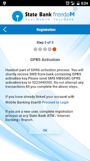
Step 3) Complete Steps 1 to 5. Enter your existing User ID and default MPIN. Choose a new PIN (can be alphanumeric).


Step 4) At step 5 it says you'll get a sms code from bank, but I did not get that. If you don't, then manually write an sms- MBREG and send to 9223440000.
You'll get an SMS from bank stating- Cannot process request. Your mobile number is already registered. Else you need to register for mobile banking freshly.

After that you should get your GPRS activation key from bank by sms.
If you don't, just follow steps 1 to 5 again. Once you've received 8 digit GPRS activation key, send sms- MBSGAC <GPRS activation key> to 9223440000.


Step 5) After that you'll get an SMS confirming GPRS now enabled for your account. You can now use SB Freedom over GPRS.


Step 6) Then you can login using your old userID and newly set MPIN (can be alphanumeric). If it asks for register, then please complete registration by visiting any nearest SBI ATM and choose Banking option and choose Mobile Banking Registration option. You can register from NetBanking also. Or visit home branch. I know it's frustrating!


Step 7) You can now login and enjoy new app!


ONE ANNOUNCEMENT!
====================
I'm a YouTube Partner from India. I've uploaded videos on Statistics,Numerical Methods,

And a series of videos showing how to use your scientific calculators Casio fx-991ES & fx-82MS to do maths easily.

Click my YouTube channel's link below to watch them.
Subscribe to my youtube channel below-

 http://www.youtube.com/sujoyn70

Please 'SUBSCRIBE' to my YouTube channel to get updates about my latest video uploads!

[Solved] % WAN interface is DSL Problem on Cisco 867VAE-K9 Router Branch WAN ISP Router

Hi,

I'm Sujoy from India and today I'll tell you how to fix a problem with Cisco 867VAE-K9 router. While configuring IP address and giving no shutdown command on GigabitEthernet1 interface, I got the error message % WAN interface is DSL and could not enable the interface. How did I fix it? Read below.

Physical overview of Cisco 867VAE-K9


If you look at the picture, you'll see the GE1 (GigabitEthernet1) is marked as WAN. So why can't I assign an IP address on that? Because Cisco 867VAE-K9 router supports both DSL and Ethernet medium for WAN connectivity, and DSL is default. So you've to convert it to Ethernet by giving command- Router(config)#wan mode ethernet
Below is the command output captured using PuTTy. Notice I've set speed to 10 (Mbps). Sometimes you need to manually set speed to 10Mbps and duplex full or as instructed by your ISP.

Router(config)#wan mode ethernet
% DSL interfaces will be disabled.
Router(config)#
*Mar  9 10:39:06.907: %CONTROLLER-5-UPDOWN: Controller VDSL 0, changed state to administratively down
Router(config)#int gigabitEthernet 1
Router(config-if)#ip address 10.75.0.162 255.255.255.252
Router(config-if)#no shut
Router(config-if)#
*Mar  9 10:41:05.979: %LINK-3-UPDOWN: Interface GigabitEthernet1, changed state to up
Router(config-if)#speed 10
Router(config-if)#duplex full

Don't forget to save changes by write command after all configurations are done by command- Router# write

ONE ANNOUNCEMENT!
====================
I'm a YouTube Partner from India. I've uploaded videos on Statistics,Numerical Methods,

And a series of videos showing how to use your scientific calculators Casio fx-991ES & fx-82MS to do maths easily.

Click my YouTube channel's link below to watch them.
Subscribe to my youtube channel below-

 http://www.youtube.com/sujoyn70

Please 'SUBSCRIBE' to my YouTube channel to get updates about my latest video uploads!